• Home
  • Download PDF
  • Order CD-ROM
  • Order in Print
TRACK ADJUSTER AND RECOIL ASSEMBLY SERVICE
Figure 2. Forcing Screws.

Field Maintenance Manual D7R Dozer Type I With Winch and Type II With Ripper
Page Navigation
  636    637    638    639    640  641  642    643    644    645    646  
img
.
TM 5-2410-241-23-2
0134
REMOVAL
000134
N OT E
This procedure will remove one track adjuster and recoil assembly. Follow same
procedure for additional track adjuster and recoil assembly.
Guides are located both inside and outside of track frame.
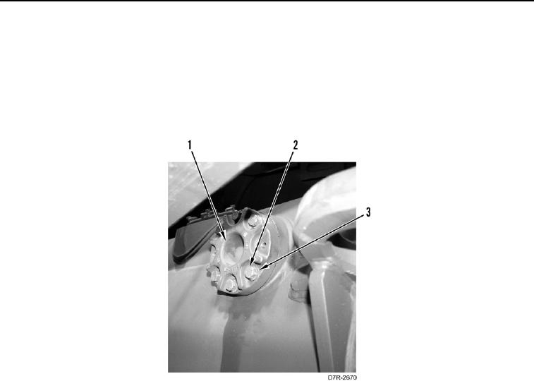
1. Remove 12 bolts (Figure 1, Item 2) and washers (Figure 1, Item 3) from 2 guides (Figure 1, Item 1).
Figure 1. Track Frame Guide.
0134
0134-2


Privacy Statement
Press Release
Contact

© Copyright Integrated Publishing, Inc.. All Rights Reserved.