
6
TM 5-2410-241-23-2
FIELD MAINTENANCE
-
BACKUP ALARM HARNESS REPLACEMENT
016
8
Removal, Cleaning and Inspection, Installation
INITIAL SETUP
References
Tools and Special Tools
0
0
Tool Kit, General Mechanic's
WP 0295
0
(WP 0302, Item 65)
0
Equipment Condition
0
Materials/Parts
Machine parked (TM 5-2410-241-10)
0
0
Rag, Wiping (WP 0303, Item 24)
0
Drawing Required
0
Tag, Marker (WP 0303, Item 34)
0
TM 5-2410-241-24P, Figure 96
Tiedown Strap (WP 0303, Item 36)
0
0
Estimated Time to Complete
0
0.5 Hr
0
REMOVAL
000168
N OT E
Tag and mark electrical connectors to aid installation.
Note harness routing to aid installation.
Mark location and number of tiedown straps before removal.
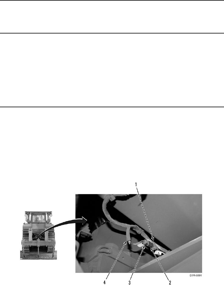
1. Remove tiedown straps (Figure 1, Item 1) from harness (Figure 1, Item 4). Discard tiedown straps.
2. Disconnect connector (Figure 1, Item 2) from connector (Figure 1, Item 3).
3. Position harness (Figure 1, Item 4) aside.
Figure 1. Frame Connector.
0168