
TM 5-2410-241-23-2
0167
INSTALLATION
000167
N OT E
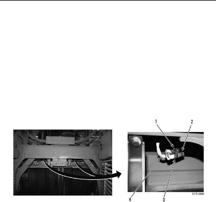
Install connectors as noted during removal.
Route harness as noted during removal.
1. Install harness (Figure 4, Item 3) on machine.
2. Connect connector Figure 4, Item 5) on horn (Figure 4, Item 6).
3. Connect connector (Figure 4, Item 1) on horn (Figure 4, Item 2).
4. Install new tiedown strap (Figure 4, Item 4) on harness (Figure 4, Item 3).
N OT E
Install connectors as noted during removal.
Route harness as noted during removal.
5. Position harness (Figure 5, Item 4) on machine.
6. Connect two connectors (Figure 5, Item 2) on connectors (Figure 5, Item 3) and harness (Figure 5, Item 4).
7. Install new tiedown straps (Figure 5, Item 1) on harness (Figure 5, Item 4).
Figure 5. Light Connectors.
0167