
TM 5-2410-241-23-2
0171
SUPPLY VALVE DISASSEMBLY
000171
N OT E
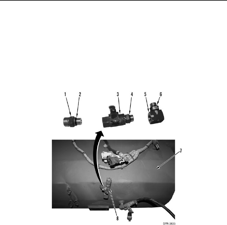
Note position and orientation of fittings and valves to aid in assembly.
1. Remove supply valve (Figure 9, Item 8) from fuel tank (Figure 9, Item 7).
2. Remove O-ring (Figure 9, Item 6) from fitting (Figure 9, Item 5). Discard O-ring.
3. Remove fitting (Figure 9, Item 1) from supply valve (Figure 9, Item 3).
4. Remove O-ring (Figure 9, Item 2) from fitting (Figure 9, Item 1). Discard O-ring.
5. Remove fitting (Figure 9, Item 5) from supply valve (Figure 9, Item 3).
6. Remove O-ring (Figure 9, Item 4) from supply valve (Figure 9, Item 3). Discard O-ring.
Figure 9. Supply Valve.
0171
END OF TASK