
TM 5-2410-241-23-2
0176
ASSEMBLY CONTINUED
N OT E
Install connectors as tagged during removal.
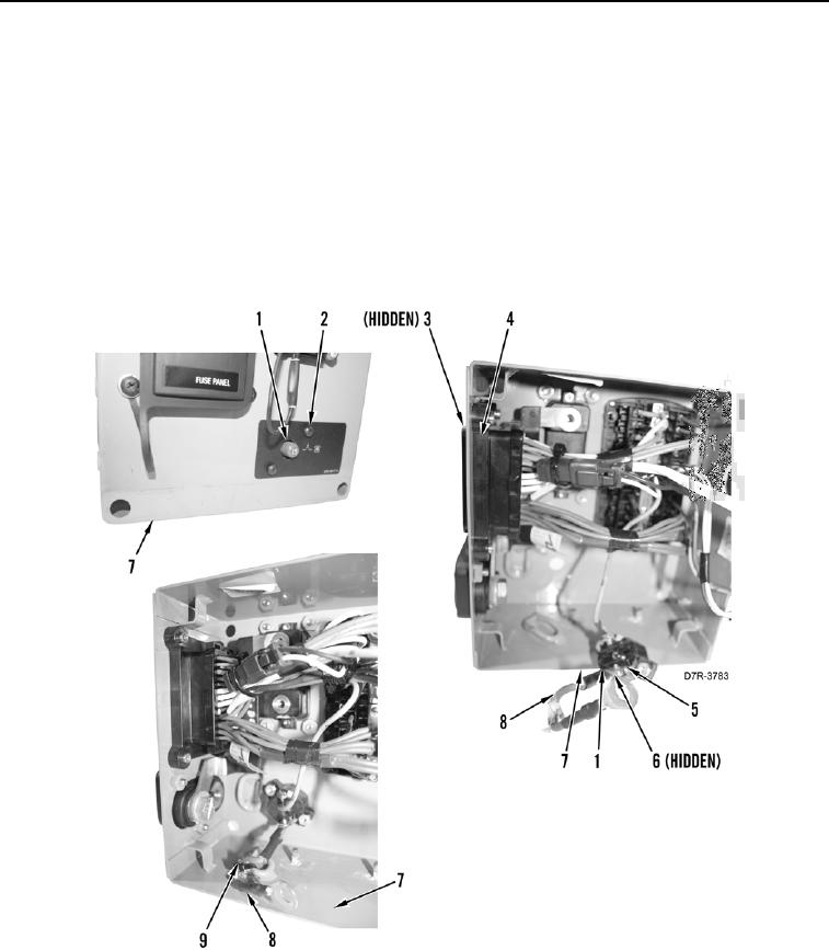
11. Install harness connector (Figure 12, Item 4) and four bolts (Figure 12, Item 3) on fuse box (Figure 12, Item 7).
12. Install two washers (Figure 12, Item 6), wires (Figure 12, Item 8), and bolts (Figure 12, Item 5) on blower motor
circuit breaker (Figure 12, Item 1).
13. Install wire (Figure 12, Item 8) and new tiedown strap (Figure 12, Item 9) on fuse box (Figure 12, Item 7).
14. Install blower motor circuit breaker (Figure 12, Item 1) and two bolts (Figure 12, Item 2) on fuse box (Figure 12,
Item 7).
Figure 12. Blower Motor Circuit Breaker.
0176