
TM 5-2410-241-23-2
0176
INSTALLATION
000176
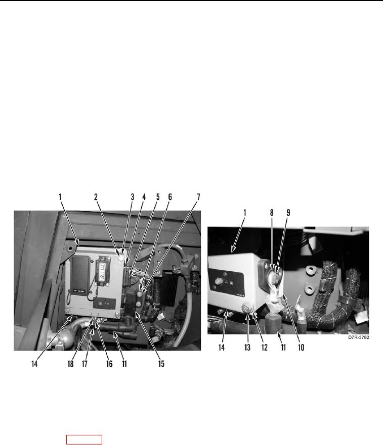
1. Install isolator (Figure 17, Item 10) on machine.
2. Install fuse box (Figure 17, Item 1), two washers (Figure 17, Item 3), and upper bolts (Figure 17, Item 2) on
machine.
3. Install bracket (Figure 17, Item 14), two washers (Figure 17, Item 12), and lower bolts (Figure 17, Item 13) on
fuse box (Figure 17, Item 1).
N OT E
Install connectors as tagged in removal.
4. Install two cables (Figure 17, Item 11), washers (Figure 17, Item 8), and bolts (Figure 17, Item 9) on fuse box.
(Figure 17, Item 1)
5. Install cover (Figure 17, Item 15), two washers (Figure 17, Item 7), and bolts (Figure 17, Item 6) on machine.
6. Install connector (Figure 17, Item 4) on fuse box (Figure 17, Item 1) and tighten bolt (Figure 17, Item 5).
7. Install two clips (Figure 17, Item 17), cables (Figure 17, Item 11), washers (Figure 17, Item 16), and new
locknuts (Figure 17, Item 18) on bracket (Figure 17, Item 14).
Figure 17. Fuse Box Connections.
0176
END OF TASK
FOLLOW-ON TASKS
000176
1. Install batteries (WP 0155).
2. Verify correct operation of machine (TM 5-2410-241-10).
END OF TASK
END OF WORK PACKAGE