
TM 5-2410-241-23-2
0178
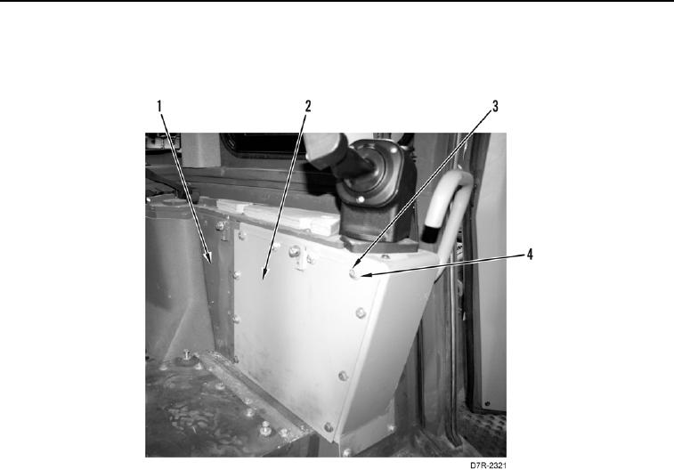
REMOVAL CONTINUED
3. Remove 10 bolts (Figure 2, Item 3), washers (Figure 2, Item 4), and left cover plate (Figure 2, Item 2) from
console (Figure 2, Item 1).
Figure 2. Left Cover Plate.
0178
N OT E
Tag and mark electrical connectors to aid installation.
Note wiring harness routing to aid installation.
Mark location and number of tiedown straps before removal.
4. Remove tiedown straps (Figure 3, Item 9) from wiring harness (Figure 3, Item 13). Discard tiedown straps.
5. Disconnect connectors (Figure 3, Items 6, 7, 8, and 10) from wiring harness (Figure 3, Item 13).
6. Loosen bolt (Figure 3, Item 4) until connector (Figure 3, Item 5) is removed from powertrain control module
(Figure 3, Item 1).
7. Loosen bolt (Figure 3, Item 2) until connector (Figure 3, Item 3) is removed from powertrain control module
(Figure 3, Item 1).
8. Loosen bolt (Figure 3, Item 15) until connector (Figure 3, Item 16) is removed from bulkhead (Figure 3,
Item 21).
9. Remove two screws (Figure 3, Item 17) and washers (Figure 3, Item 18), and disconnect connector (Figure 3,
Item 19) from bulkhead (Figure 3, Item 21).
10. Remove wiring harness (Figure 3, Item 13) from machine cab.
11. Disconnect resistor (Figure 3, Item 14) from wiring harness (Figure 3, Item 13).
12. Remove harness (Figure 3, Item 11) from connector (Figure 3, Item 12).
13. Remove cap (Figure 3, Item 20) from connector (Figure 3, Item 19).