
TM 5-2410-241-23-2
0178
INSTALLATION
000178
N OT E
Install electrical connectors as noted during removal.
Install wiring harness as noted during removal.
Install tiedown straps as noted during removal.
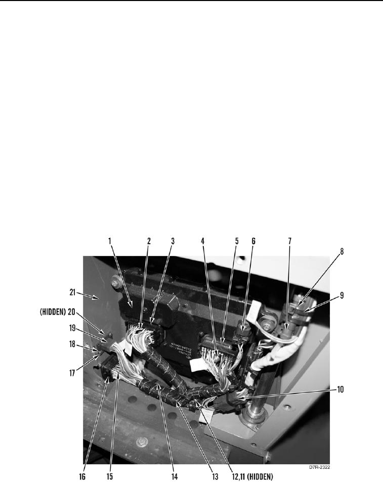
1. Install cap (Figure 4, Item 20) on connector (Figure 4, Item 19).
2. Install harness (Figure 4, Item 11) on connector (Figure 4, Item 12).
3. Install resistor (Figure 4, Item 14) on wiring harness (Figure 4, Item 13).
4. Position wiring harness (Figure 4, Item 13) inside bulkhead (Figure 4, Item 21).
5. Connect connector (Figure 4, Item 19) to bulkhead (Figure 4, Item 21) and install two washers (Figure 4,
Item 18) and screws (Figure 4, Item 17).
6. Plug in connector (Figure 4, Item 16) and tighten bolt (Figure 4, Item 15) until connector is installed on
bulkhead (Figure 4, Item 21).
7. Plug in connector (Figure 4, Item 3) and tighten bolt (Figure 4, Item 2) until connector is installed on powertrain
control module (Figure 4, Item 1).
8. Plug in connector (Figure 4, Item 5) and tighten bolt (Figure 4, Item 4) until connector is installed on powertrain
control module (Figure 4, Item 1).
9. Connect connectors (Figure 4, Items 6, 7, 8, and 10) to wiring harness (Figure 4, Item 11).
Figure 4. Powertrain Control Wiring Harness.
0178