
TM 5-2410-241-23-2
0188
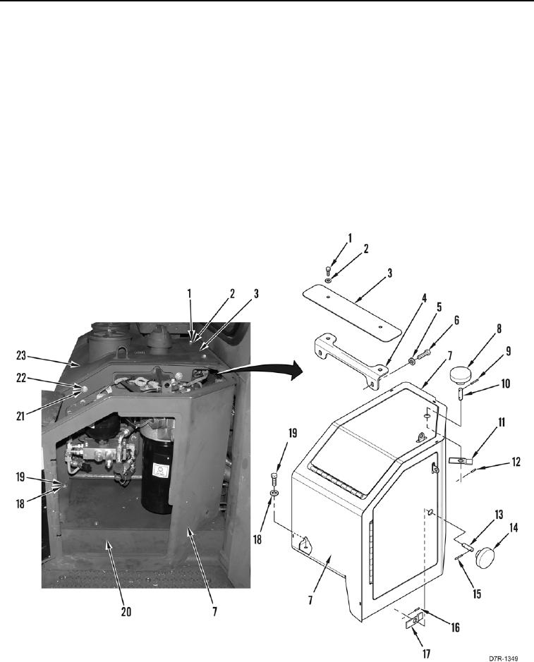
INSTALLATION CONTINUED
3. Install stud (Figure 4, Item 13), knob (Figure 4, Item 14), nut plate (Figure 4, Item 17), and two pins (Figure 4,
Items 15 and 16) on hydraulic tank enclosure (Figure 4, Item 7).
4. Install stud (Figure 4, Item 10), knob (Figure 4, Item 8), nut plate (Figure 4, Item 11), and two pins (Figure 4,
Items 9 and 12), on hydraulic tank enclosure (Figure 4, Item 7).
5. Install hydraulic tank enclosure (Figure 4, Item 7) on hydraulic tank (Figure 4, Item 23) and fender (Figure 4,
Item 20).
6. Install two washers (Figure 4, Item 22) and bolts (Figure 4, Item 21), on hydraulic tank enclosure (Figure 4,
Item 7), and hydraulic tank (Figure 4, Item 23).
7. Install two washers (Figure 4, Item 18) and bolts (Figure 4, Item 19), on hydraulic tank enclosure (Figure 4,
Item 7) and fender (Figure 4, Item 20).
8. Install cover (Figure 4, Item 4), two washers (Figure 4, Item 5), and bolts (Figure 4, Item 6) on machine.
9. Install cover (Figure 4, Item 3), two washers (Figure 4, Item 2), and bolts (Figure 4, Item 1) on machine.
Figure 4. Enclosure.
0188