
TM 5-2410-241-23-2
0189
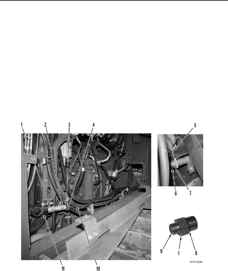
LOWER HYDRAULIC OIL COOLER LINE REMOVAL
000189
N OT E
Mark location and number of tiedown straps before removal.
1. Disconnect lower line (Figure 4, Item 2) from fitting (Figure 4, Item 1).
2. Remove connector (Figure 4, Item 1) from hydraulic oil cooler (Figure 4, Item 11).
3. Remove two O-rings (Figure 4, Items 8 and 9) from fitting (Figure 4, Item 1). Discard O-rings.
4. Remove tiedown strap (Figure 4, Item 3) and lower line (Figure 4, Item 2) from swivel (Figure 4, Item 4).
Discard tiedown strap.
5. Remove tiedown strap (Figure 4, Item 3) from swivel (Figure 4, Item 4). Discard tiedown strap.
N OT E
Note location of clamps to aid installation.
6. Remove two bolts (Figure 4, Item 6), washers (Figure 4, Item 7), and clamps (Figure 4, Item 5) from upper
(Figure 4, Item 10) and lower (Figure 4, Item 2) lines.
Figure 4. Lower Hydraulic Oil Cooler Line Connector.
0189