
TM 5-2410-241-23-2
0189
LOWER HYDRAULIC OIL COOLER LINE INSTALLATION
000189
WARN I N G
Lubricating/hydraulic oils used in performance of maintenance can be very slippery.
Immediately wipe up any spills. Failure to follow this warning may result in injury to
personnel.
N OT E
Install tubes and fittings as noted during removal.
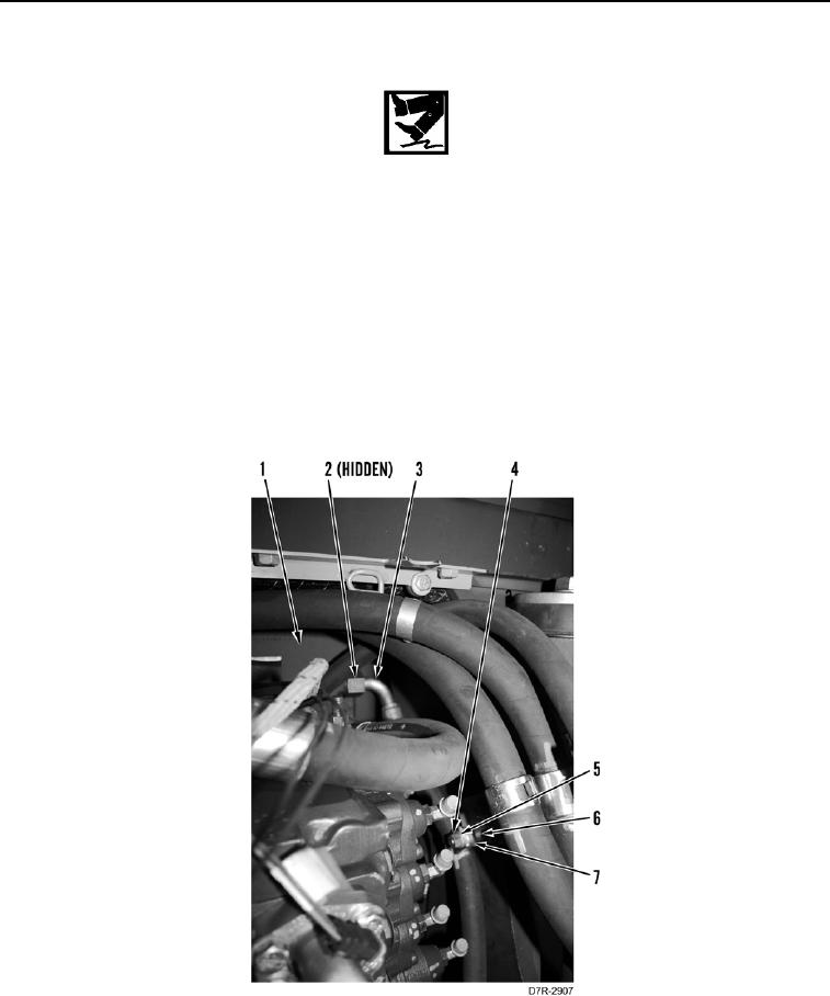
1. Install new O-ring (Figure 8, Item 2) on hydraulic tank (Figure 8, Item 1).
2. Position lower line (Figure 8, Item 3) on machine.
3. Connect lower line (Figure 8, Item 3) to hydraulic tank (Figure 8, Item 1).
4. Install spacer (Figure 8, Item 6), lower line (Figure 8, Item 3), clamp (Figure 8, Item 7), washer (Figure 8,
Item 5), and nut (Figure 8, Item 4) on machine.
Figure 8. Lower Hydraulic Oil Cooler Line at Hydraulic Tank.
0189