
TM 5-2410-241-23-2
0189
UPPER HYDRAULIC OIL COOLER LINE INSTALLATION
000189
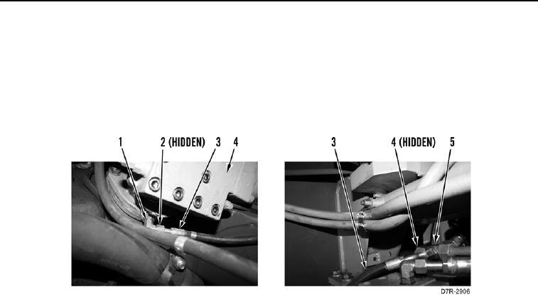
1. Install two new O-rings (Figure 12, Items 2 and 4) on elbow (Figure 12, Item 1) and tee (Figure 12, Item 5).
2. Position rear upper line (Figure 12, Item 3) on machine.
3. Connect rear upper line (Figure 12, Item 3) to elbow (Figure 12, Item 1) on counterbalance valve (Figure 12,
Item 4).
4. Connect rear upper line (Figure 12, Item 3) to tee (Figure 12, Item 5).
Figure 12. Upper Hydraulic Oil Cooler Line at Counterbalance Valve.
0189