
TM 5-2410-241-23-2
0189
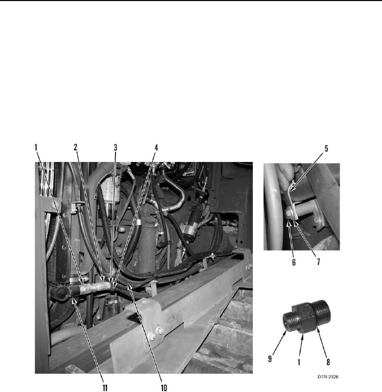
LOWER HYDRAULIC OIL COOLER LINE INSTALLATION CONTINUED
7. Install upper (Figure 11, Item 10) and lower lines (Figure 11, Item 2), two clamps (Figure 11, Item 5), washers
(Figure 11, Item 7), and bolts (Figure 11, Item 6) on machine.
N OT E
Note location of clamps to aid installation.
8. Install lower line (Figure 11, Item 2) and new tiedown strap (Figure 11, Item 3) on swivel (Figure 11, Item 4).
9. Install two new O-rings (Figure 11, Items 8 and 9) on fitting (Figure 11, Item 1).
10. Install connector (Figure 11, Item 1) on hydraulic oil cooler (Figure 11, Item 11).
11. Connect lower line (Figure 11, Item 2) to fitting (Figure 11, Item 1).
Figure 11. Lower Hydraulic Oil Cooler Line Connector.
0189
END OF TASK