
TM 5-2410-241-23-2
0189
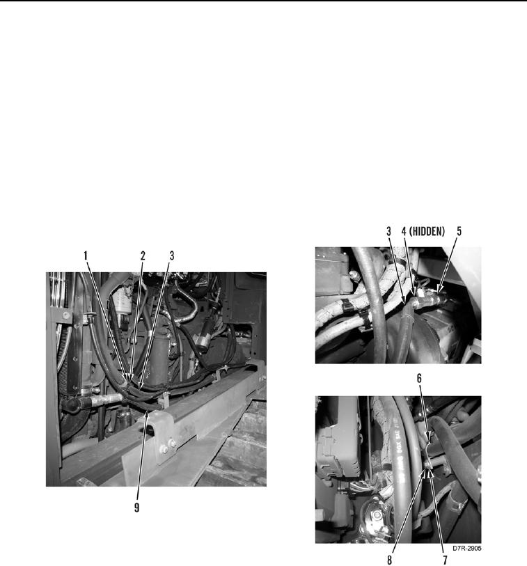
UPPER HYDRAULIC OIL COOLER LINE INSTALLATION CONTINUED
5. Position front upper line (Figure 13, Item 3) on machine.
6. Install new O-ring (Figure 13, Item 4) on tee (Figure 13, Item 5).
7. Connect front upper line (Figure 13, Item 3) to tee (Figure 13, Item 5).
N OT E
Install clamps as noted during removal.
Install tiedown straps as noted during removal.
8. Install two clamps (Figure 13, Item 6), washers (Figure 13, Item 7), and bolts (Figure 13, Item 8) on front upper
and lower lines (Figure 13, Items 3 and 9).
9. Install two new tiedown straps (Figure 13, Item 2) on front upper line (Figure 13, Items 3) and swivel
(Figure 13, Item 1).
Figure 13. Upper Hydraulic Oil Cooler Line.
0189