
TM 5-2410-241-23-2
0190
REMOVAL CONTINUED
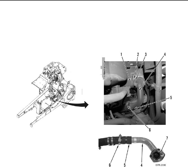
4. Remove four bolts (Figure 2, Item 2), washers (Figure 2, Item 3), and lower hydraulic suction line (Figure 2,
Item 4) from implement pump (Figure 2, Item 1).
5. Remove lower hydraulic suction line (Figure 2, Item 4) and hose (Figure 2, Item 5) from machine.
6. Remove O-ring (Figure 2, Item 7) from lower hydraulic suction line (Figure 2, Item 4). Discard O-ring.
7. Remove two clamps (Figure 2, Item 6) and hose (Figure 2, Item 5) from lower hydraulic suction line (Figure 2,
Item 4).
Figure 2. Lower Hydraulic Suction Line.
0190