
TM 5-2410-241-23-2
0189
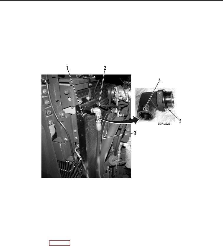
UPPER HYDRAULIC OIL COOLER LINE INSTALLATION CONTINUED
N OT E
Install fitting as noted during removal.
10. Install two new O-rings (Figure 14, Items 4 and 5) on elbow (Figure 14, Item 2).
11. Install elbow (Figure 14, Item 2) on hydraulic oil cooler (Figure 14, Item 1).
12. Connect front upper line (Figure 14, Item 3) on elbow (Figure 14, Item 2).
Figure 14. Upper Hydraulic Oil Cooler Line Elbow.
0189
END OF TASK
FOLLOW-ON TASKS
000189
1. Install engine enclosure left door guard (WP 0202).
2. Install front and rear floor plates (WP 0230 and WP 0231).
3. Install right platform access panels (WP 0208).
4. Install bottom guards (WP 0199).
5. Fill hydraulic system (WP 0184).
6. Verify correct operation of machine (TM 5-2410-241-10).
END OF TASK
END OF WORK PACKAGE