• Home
  • Download PDF
  • Order CD-ROM
  • Order in Print
Figure 4. Lines.
Figure 6. Upper Hydraulic Suction Line at Hydraulic Tank.

Field Maintenance Manual D7R Dozer Type I With Winch and Type II With Ripper
Page Navigation
  1144    1145    1146    1147    1148  1149  1150    1151    1152    1153    1154  
img
.
TM 5-2410-241-23-2
0190
REMOVAL CONTINUED
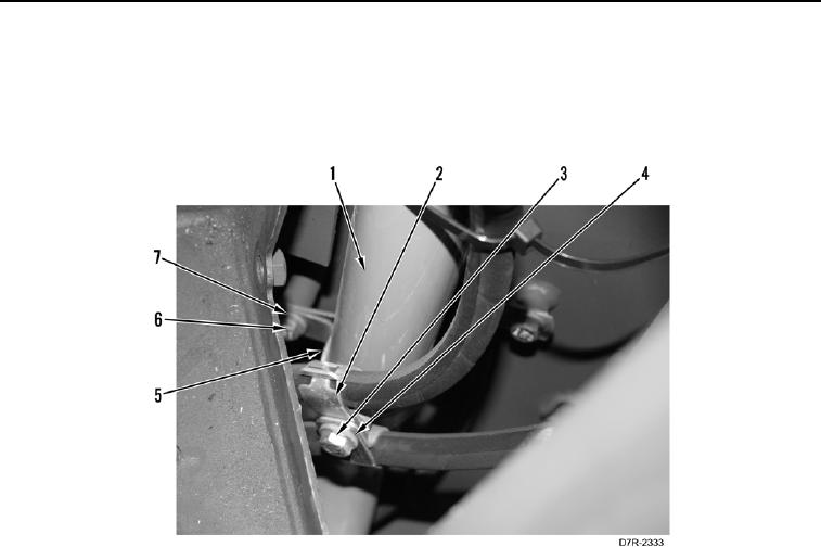
16. Remove bolt (Figure 5, Item 3), washer (Figure 5, Item 4), and two clamps (Figure 5, Item 2) from upper
hydraulic suction line (Figure 5, Item 1).
17. Remove bolt (Figure 5, Item 6), washer (Figure 5, Item 7), and clamp (Figure 5, Item 5) from upper hydraulic
suction line (Figure 5, Item 1) and machine.
Figure 5. Right Front Panel Clamps.
0190
0190-7


Privacy Statement
Press Release
Contact

© Copyright Integrated Publishing, Inc.. All Rights Reserved.