
TM 5-2410-241-23-2
0190
INSTALLATION CONTINUED
N OT E
Install all hoses, tubes, and fittings as noted during removal.
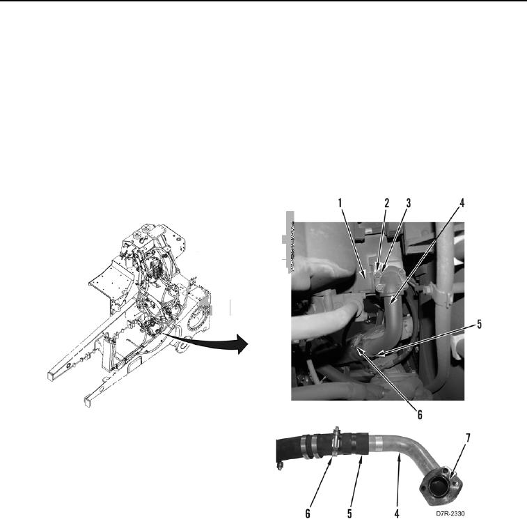
14. Install hose (Figure 10, Item 5) and two clamps (Figure 10, Item 6) on lower hydraulic suction line (Figure 10,
Item 4).
15. Install new O-ring (Figure 10, Item 7) on lower hydraulic suction line (Figure 10, Item 4).
16. Position lower hydraulic suction line (Figure 10, Item 4) and hose (Figure 10, Item 5) on machine.
17. Install lower hydraulic suction line (Figure 10, Item 4), four washers (Figure 10, Item 3), and bolts (Figure 10,
Item 2) on implement pump (Figure 10, Item 1).
Figure 10. Lower Hydraulic Suction Line.
0190
N OT E
Install all hoses, tubes, and fittings as noted during removal.
18. Install hose (Figure 11, Item 7) and two clamps (Figure 11, Item 6) on upper hydraulic suction line (Figure 11,
Item 1).