
TM 5-2410-241-23-2
0190
INSTALLATION CONTINUED
N OT E
Install all hoses, lines, and tubes as noted during removal.
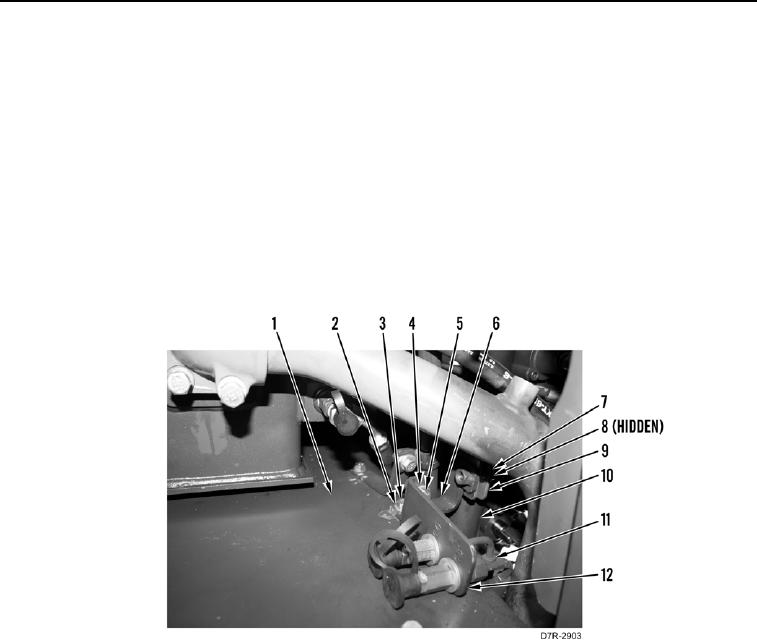
10. Install bracket (Figure 9, Item 6), washer (Figure 9, Item 2), and bolt (Figure 9, Item 3) on right fender
(Figure 9, Item 1).
11. Position test port bracket (Figure 9, Item 12) and test port lines (Figure 9, Item 11) on right fender (Figure 9,
Item 1).
12. Install test port bracket (Figure 9, Item 12), washer (Figure 9, Item 4), and bolt (Figure 9, Item 5) on bracket
(Figure 9, Item 6).
13. Install clamp (Figure 9, Item 9), washer (Figure 9, Item 8), and bolt (Figure 9, Item 7) on filler tube (Figure 9,
Item 10).
Figure 9. Brackets.
0190