• Home
  • Download PDF
  • Order CD-ROM
  • Order in Print
Figure 1. Implement Pump to Hydraulic Tank.
Figure 5. Hydraulic Tank.

Field Maintenance Manual D7R Dozer Type I With Winch and Type II With Ripper
Page Navigation
  1154    1155    1156    1157    1158  1159  1160    1161    1162    1163    1164  
img
.
TM 5-2410-241-23-2
0191
REMOVAL CONTINUED
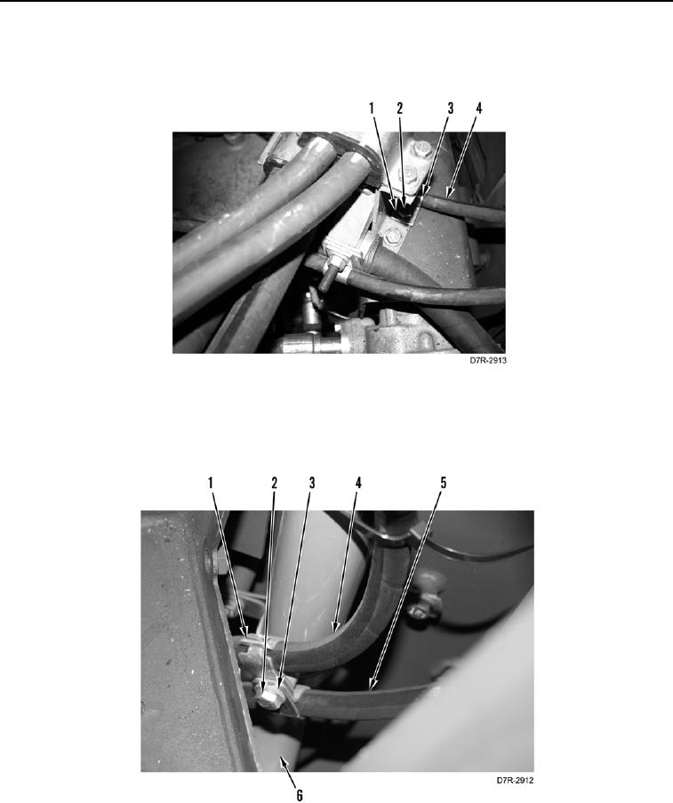
4. Remove bolt (Figure 3, Item 2), washer (Figure 3, Item 1), clamp (Figure 3, Item 3), and hose (Figure 3, Item 4)
from machine.
Figure 3. Clamp.
0191
5. Remove bolt (Figure 4, Item 2), washer (Figure 4, Item 3), two retaining straps (Figure 4, Item 1), and two
hoses (Figure 4, Items 4 and 5) from hydraulic suction line (Figure 4, Item 6).
Figure 4. Clamps at Filler Tube.
0191
0191-4


Privacy Statement
Press Release
Contact

© Copyright Integrated Publishing, Inc.. All Rights Reserved.