
TM 5-2410-241-23-2
0191
REMOVAL CONTINUED
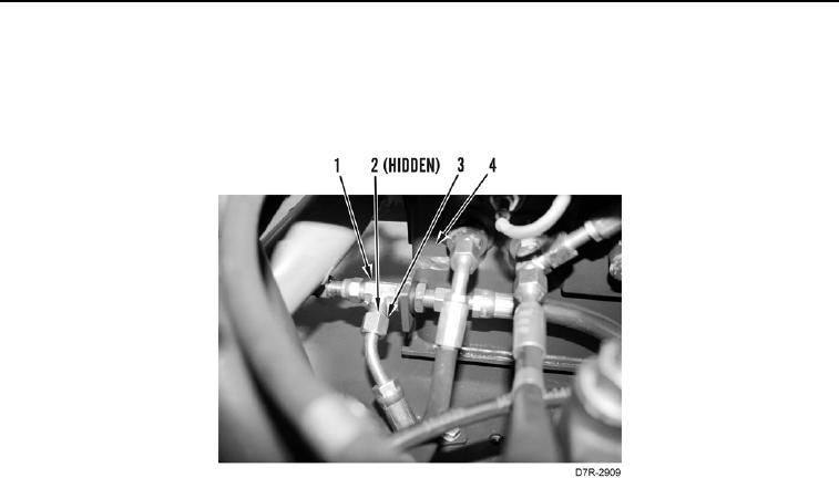
6. Disconnect hose (Figure 5, Item 3) from tee (Figure 5, Item 1) at hydraulic tank (Figure 5, Item 4). Remove
hose from machine.
7. Remove O-ring (Figure 5, Item 2) from tee (Figure 5, Item 1). Discard O-ring.
Figure 5. Hydraulic Tank.
0191
END OF TASK
CLEANING AND INSPECTION
000191
Clean and inspect all parts IAW Mechanical General Maintenance Instructions (WP 0295).
END OF TASK
INSTALLATION
000191
N OT E
Install hose and tee as noted during removal.
1. Install new O-ring (Figure 5, Item 2) on tee (Figure 5, Item 1).
2. Position hose (Figure 5, Item 3) on machine.
3. Connect hose (Figure 5, Item 3) on tee (Figure 5, Item 1) at hydraulic tank. (Figure 5, Item 4).