
TM 5-2410-241-23-2
0195
INSTALLATION CONTINUED
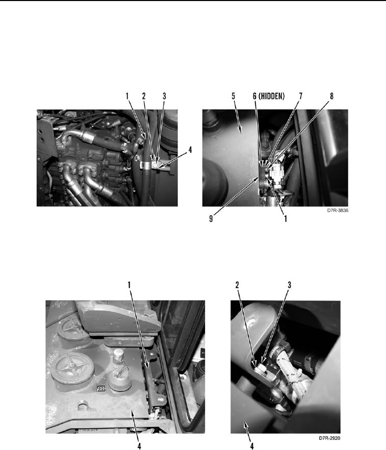
4. Install new O-ring (Figure 7, Item 6) on hose (Figure 7, Item 1).
5. Install hose (Figure 7, Item 1), flange (Figure 7, Item 9), four washers (Figure 7, Item 7), and bolts (Figure 7,
Item 8) on hydraulic tank (Figure 7, Item 5).
6. Install two spring tension clips (Figure 7, Item 4), hose (Figure 7, Item 1), washer (Figure 7, Item 2), and bolt
(Figure 7, Item 3) on machine.
Figure 7. Hydraulic Tank.
0195
7. Install bracket (Figure 8, Item 1), two washers (Figure 8, Item 2), and bolts (Figure 8, Item 3) on hydraulic tank
(Figure 8, Item 4).
Figure 8. Bracket.
0195