
TM 5-2410-241-23-2
0196
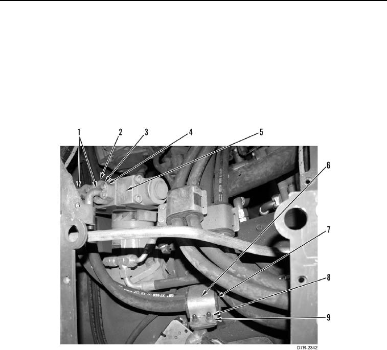
REMOVAL CONTINUED
N OT E
Removal steps for two upper lines are identical.
1. Remove eight bolts (Figure 1, Item 3), washers (Figure 1, Item 4), and two flanges (Figure 1, Item 2) from
counterbalance valve (Figure 1, Item 5).
2. Disconnect two hoses (Figure 1, Item 1) from counterbalance valve (Figure 1, Item 5).
3. Remove two nuts (Figure 1, Item 8), washers (Figure 1, Item 9), clamp (Figure 1, Item 6), and grommet
(Figure 1, Item 7) from two hoses (Figure 1, Item 1).
Figure 1. Counterbalance Valve.
0196