
TM 5-2410-241-23-2
0196
INSTALLATION CONTINUED
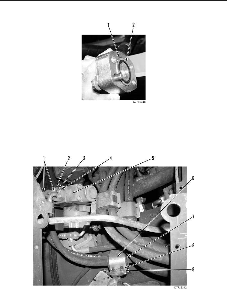
4. Lubricate and install two new O-rings (Figure 5, Item 2) on hoses (Figure 5, Item 1).
Figure 5. Flange.
0196
5. Install clamp (Figure 6, Item 6), grommet (Figure 6, Item 7), two washers (Figure 6, Item 9), and nuts (Figure 6,
Item 8) on two hoses (Figure 6, Item 1).
6. Connect two hoses (Figure 6, Item 1) to counterbalance valve (Figure 6, Item 5).
7. Install two flanges (Figure 6, Item 2), eight washers (Figure 6, Item 4), and bolts (Figure 6, Item 3) on
counterbalance valve (Figure 6, Item 5).
Figure 6. Counterbalance Valve.
0196