
TM 5-2410-241-23-2
0196
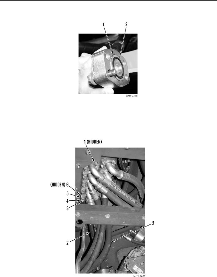
REMOVAL CONTINUED
4. Remove and discard two O-rings (Figure 2, Item 2) from hoses (Figure 2, Item 1).
Figure 2. Flange.
0196
5. Remove eight bolts (Figure 3, Item 3), washers (Figure 3, Item 4), and two flanges (Figure 3, Item 5) from main
control valve (Figure 3, Item 1).
6. Disconnect two hoses (Figure 3, Item 2) from main control valve (Figure 3, Item 1).
7. Remove and discard two O-rings (Figure 3, Item 6) from hoses (Figure 3, Item 2).
Figure 3. Implement Valve.
0196