
TM 5-2410-241-23-2
0196
INSTALLATION
000196
WARN I N G
Lubricating/hydraulic oils used in performance of maintenance can be very slippery.
Immediately wipe up any spills. Failure to follow this warning may result in injury to
personnel.
N OT E
Install tubes and fittings as noted during removal.
Installation steps for two upper lines are identical.
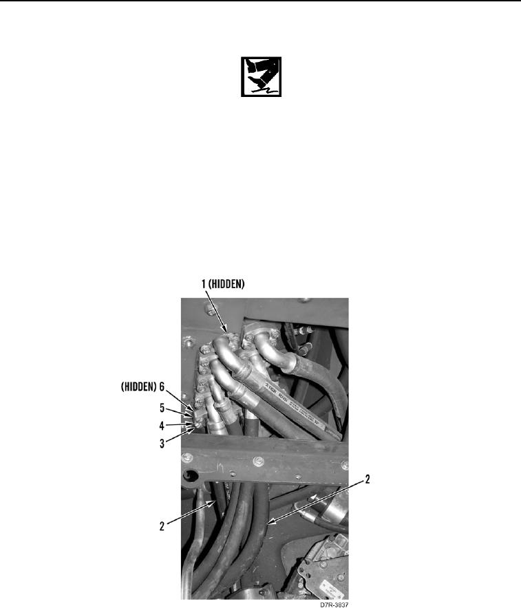
1. Lubricate and install two new O-rings (Figure 4, Item 6) on hoses (Figure 4, Item 2).
2. Connect two hoses (Figure 4, Item 2) to main control valve (Figure 4, Item 1).
3. Install two flanges (Figure 4, Item 5), eight washers (Figure 4, Item 4), and bolts (Figure 4, Item 3) on main
control valve (Figure 4, Item 1).
Figure 4. Implement Valve.
0196