
TM 5-2410-241-23-3
0197
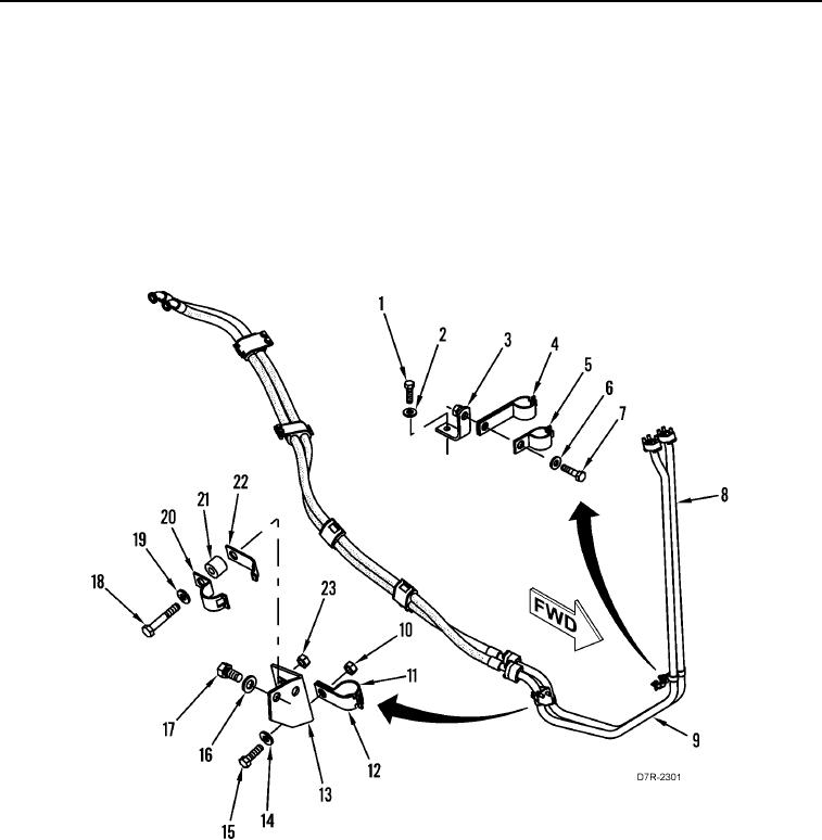
INSTALLATION CONTINUED
15. Install bracket (Figure 19, Item 13), two washers (Figure 19, Item 16), and bolts (Figure 19, Item 17) on
machine.
16. Install bolt (Figure 19, Item 18), washer (Figure 19, Item 19), spacer (Figure 19, Item 21), two retaining straps
(Figure 19, Items 20 and 22), and nut (Figure 19, Item 23) on bracket (Figure 19, Item 13).
17. Install bolt (Figure 19, Item 15), washer (Figure 19, Item 14), two retaining straps (Figure 19, Items 11 and 12),
and nut (Figure 19, Item 10) on bracket (Figure 19, Item 13).
18. Install bracket (Figure 19, Item 3), washer (Figure 19, Item 2) and bolt (Figure 19, Item 1) on machine.
19. Install two clips (Figure 19, Item 4), two retaining straps (Figure 19, Item 5), washer (Figure 19, Item 6), and
bolt (Figure 19, Item 7) on tubes (Figure 19, Items 8 and 9).
Figure 19. Tube Clamps.
0197