
TM 5-2410-241-23-3
0197
INSTALLATION CONTINUED
N OT E
Install tubes and hoses as tagged during removal.
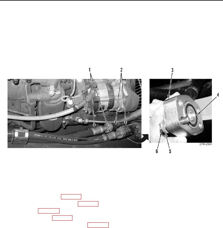
23. Install two new O-rings (Figure 22, Item 4) and connect two tubes (Figure 22, Item 2) on hoses (Figure 22,
Item 1).
24. Install two flanges (Figure 22, Item 3), eight washers (Figure 22, Item 5), and bolts (Figure 22, Item 6) on tubes
(Figure 22, Item 2).
Figure 22. Tube to Hose Connection.
0197
END OF TASK
FOLLOW-ON TASKS
000197
1. Fill with hydraulic fluid (WP 0155).
2. Install front bottom guards (WP 0199).
3. Install fire extinguisher and bracket (WP 0255).
4. Install cab seat (WP 0247).
5. Install front floor plate (WP 0230).
6. Install engine enclosure right door guard (WP 0204).
7. Verify correct operation of machine (TM 5-2410-241-10).
END OF TASK
END OF WORK PACKAGE