
TM 5-2410-241-23-3
0208
UPPER RIGHT ACCESS PANEL REMOVAL CONTINUED
N OT E
Note wiring harness routing to aid installation.
Tag and mark all electrical connections to aid installation.
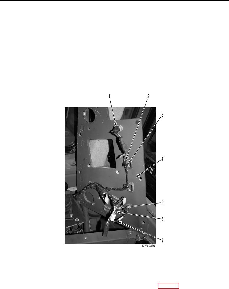
9. Remove five tiedown straps (Figure 8, Item 3) from harness (Figure 8, Item 2) and upper right access panel
(Figure 8, Item 4). Discard tiedown straps.
10. Disconnect horn switch (Figure 8, Item 1) connector from switch panel harness (Figure 8, Item 2).
11. Disconnect indicator lamp (Figure 8, Item 7) connector from switch panel harness (Figure 8, Item 2).
12. Remove nut (Figure 8, Item 6), washer (Figure 8, Item 5), and indicator lamp (Figure 8, Item 7) from upper right
access panel (Figure 8, Item 4).
13. Remove upper right access panel (Figure 8, Item 4) from machine.
Figure 8. Switch Panel Harness.
0208
END OF TASK
CLEANING AND INSPECTION
000208
Clean and inspect all parts IAW Mechanical General Maintenance Instructions (WP 0295).
END OF TASK