
TM 5-2410-241-23-3
0208
UPPER RIGHT ACCESS PANEL INSTALLATION
000208
N OT E
Route wiring harness as noted during removal.
Install electrical connections as tagged during removal.
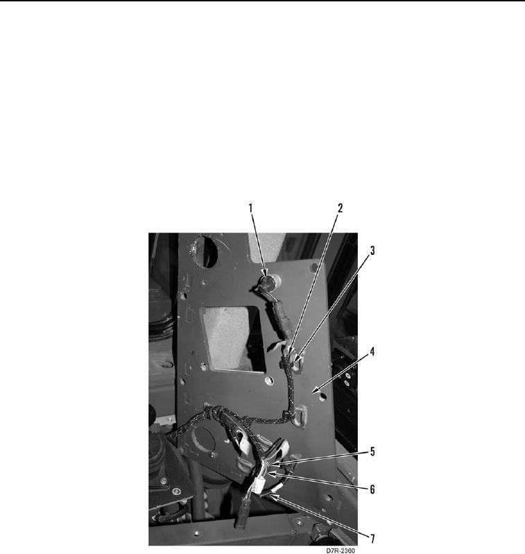
1. Position upper right access panel (Figure 9, Item 4) inside cab of machine.
2. Install indicator lamp (Figure 9, Item 7), washer (Figure 9, Item 5), and nut (Figure 9, Item 6) on upper right
access panel (Figure 9, Item 4).
3. Connect indicator lamp (Figure 9, Item 7) connector to switch panel harness (Figure 9, Item 2).
4. Connect horn switch (Figure 9, Item 1) connector to switch panel harness (Figure 9, Item 2).
5. Install five new tiedown straps (Figure 9, Item 3) on switch panel harness (Figure 9, Item 2).
Figure 9. Switch Panel Harness.
0208