
TM 5-2410-241-23-3
0214
DISASSEMBLY
000214
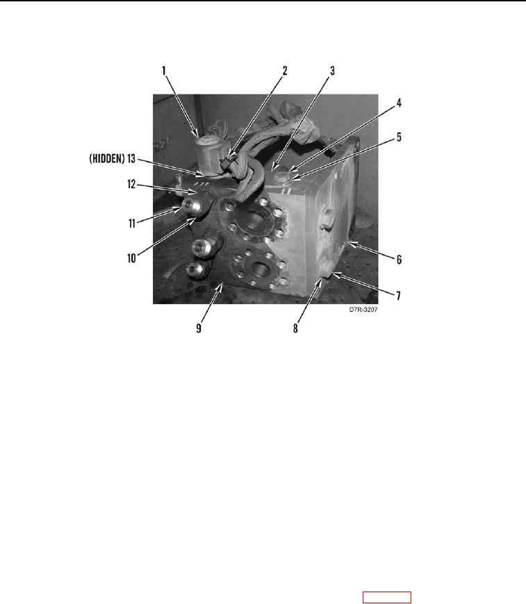
1. Remove tiedown straps (Figure 3, Item 2) from manifold (Figure 3, Item 9). Discard tiedown straps.
Figure 3. Winch Manifold.
0214
2. Remove solenoid (Figure 3, Item 1), and O-ring (Figure 3, Item 13) from manifold (Figure 3, Item 9).
3. Remove bolt (Figure 3, Item 4), washer (Figure 3, Item 5), and bracket (Figure 3, Item 3) from manifold
(Figure 3, Item 9).
4. Remove six O-rings (Figure 3, Item 11) from fittings (Figure 3, Item 10). Discard O-rings.
N OT E
Note the location and orientation of the fittings to aid in installation.
5. Remove two bolts (Figure 3, Item 7), washers (Figure 3, Item 8) and mounting bracket (Figure 3, Item 6) from
manifold (Figure 3, Item 9).
6. Remove six fittings (Figure 3, Item 10) and O-rings (Figure 3, Item 12) from manifold (Figure 3, Item 9).
END OF TASK
CLEANING AND INSPECTION
000214
Clean and inspect all parts IAW Mechanical General Maintenance Instructions (WP 0295).
END OF TASK