
TM 5-2410-241-23-3
0213
REMOVAL CONTINUED
N OT E
Tag and mark hoses to aid installation.
Cap and plug all hoses and line to prevent contamination and leaks.
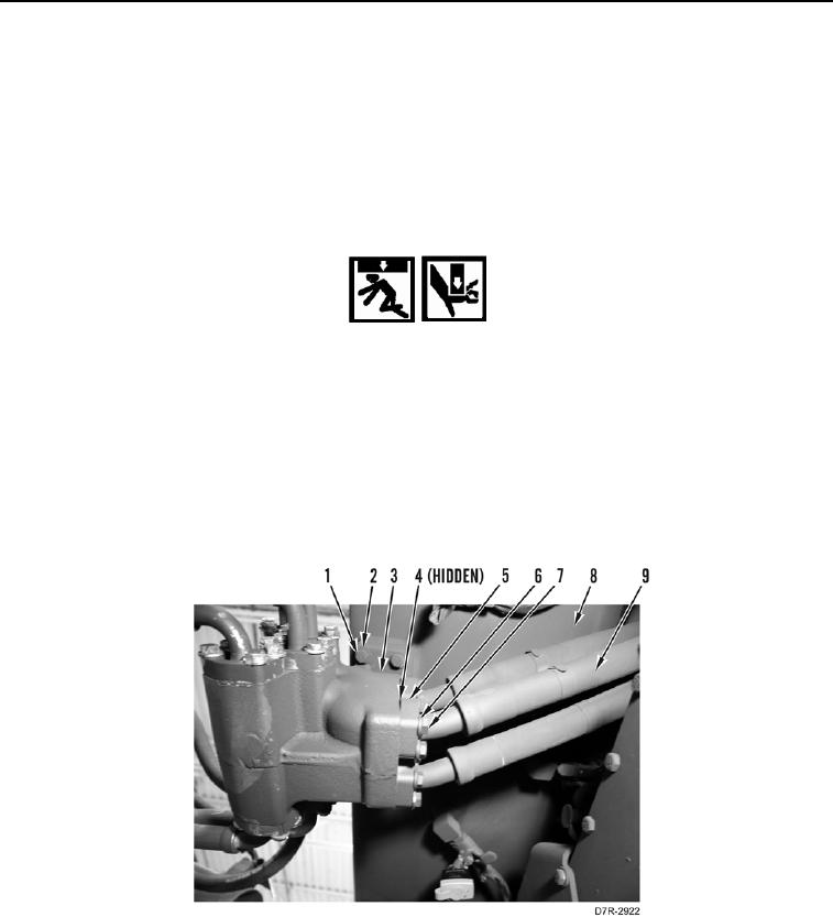
1. Remove 48 bolts (Figure 1, Item 7), washers (Figure 1, Item 6), 12 flanges (Figure 1, Item 5), and hoses
(Figure 1, Item 9) from ripper manifold (Figure 1, Item 3).
2. Remove 12 O-rings (Figure 1, Item 4) from hoses (Figure 1, Item 9). Discard O-rings.
WARN I N G
Use extreme caution when handling heavy parts. Provide adequate support and use
assistance during procedure. Ensure lifting device used is in good condition and of
suitable load capacity. Keep clear of heavy parts supported only by lifting device. Failure to
follow this warning may cause injury or death to personnel.
N OT E
Ripper manifold weighs 75 lb (34 kg).
3. With assistance, remove four bolts (Figure 1, Item 1), washers (Figure 1, Item 2), and ripper manifold (Figure 1,
Item 3) from fuel tank (Figure 1, Item 8).
Figure 1. Ripper Manifold.
0213
END OF TASK