
TM 5-2410-241-23-3
0212
INSTALLATION CONTINUED
N OT E
Valve bank will need to be positioned approximately 1 in. (25 mm) above the mounting
bracket to access and install one hose at front of valve bank.
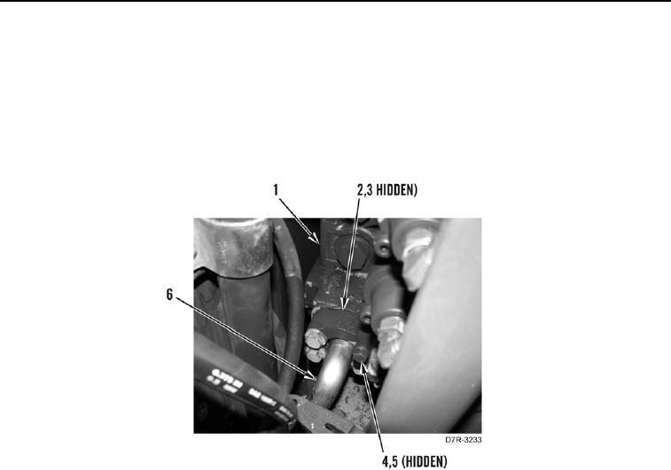
3. Install new O-ring (Figure 24, Item 3) hose (Figure 25, Item 6), flanges (Figure 24, Item 2), four washers
(Figure 24, Item 5), and bolts (Figure 24, Item 4) on valve bank (Figure 24, Item 1).
Figure 24. Hose Installation.
0212