
TM 5-2410-241-23-3
0212
INSTALLATION CONTINUED
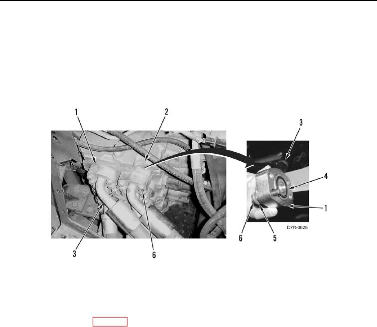
11. Install eight new O-rings (Figure 29, Item 4) on hoses (Figure 29, Item 3).
N OT E
Install hoses as noted during removal.
12. Install eight hoses (Figure 29, Item 3), 16 flanges (Figure 29, Item 1), 32 washers (Figure 29, Item 5), and bolts
(Figure 29, Item 6) on valve bank (Figure 29, Item 2).
Figure 29. Hose Installation.
0212
END OF TASK
FOLLOW-ON TASKS
000212
1. Install winch pilot valve (WP 0257).
2. Fill hydraulic system (WP 0184).
3. Verify correct operation of machine (TM 5-2410-241-10).
END OF TASK
END OF WORK PACKAGE