
TM 5-2410-241-23-3
0212
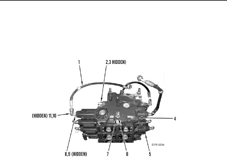
ASSEMBLY CONTINUED
13. Install cover (Figure 22, Item 4) three washers (Figure 22, Item 6), and nuts (Figure 22, Item 7) on valve bank
assembly (Figure 22, Item 5).
14. Install seven new O-rings (Figure 22, Item 9) and fittings (Figure 22, Item 8) on valve bank (Figure 22, Item 5).
15. Install two new O-rings (Figure 22, Item 3) and fittings (Figure 22, Item 2) on cover (Figure 22, Item 4).
16. Install three new O-rings (Figure 22, Item 11) on fittings (Figure 22, Item 10), and connect three hoses
(Figure 22, Item 1) to fittings.
Figure 22. Valve Bank Cover Installation.
0212
END OF TASK