• Home
  • Download PDF
  • Order CD-ROM
  • Order in Print
Figure 17. Steering Control Valve Installation.
Figure 20. Winch Control Valve Manifold.

Field Maintenance Manual 3 D7R Dozer Type I With Winch and Type II With Ripper
Page Navigation
  252    253    254    255    256  257  258    259    260    261    262  
img
.
TM 5-2410-241-23-3
0212
ASSEMBLY CONTINUED
N OT E
Install O-rings as noted during disassembly.
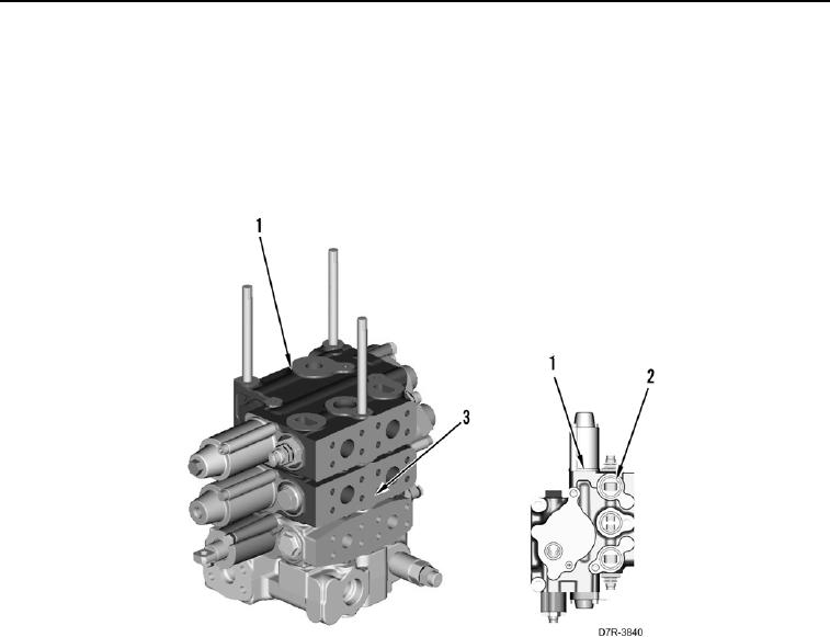
8. Install seven new O-rings (Figure 19, Item 2) on valve (Figure 19, Item 1).
9. Install valve (Figure 19, Item 1) on control valve assembly (Figure 19, Item 3).
Figure 19. Bulldozer Tilt Control Valve Manifold.
0212
0212-18


Privacy Statement
Press Release
Contact

© Copyright Integrated Publishing, Inc.. All Rights Reserved.