Home
Download PDF
Order CD-ROM
Order in Print
Figure 20. Winch Control Valve Manifold.
Figure 22. Valve Bank Cover Installation.
Field Maintenance Manual 3 D7R Dozer Type I With Winch and Type II With Ripper
Page Navigation
254
255
256
257
258
259
260
261
262
263
264
TM
5-2410-241-23-3
0212
ASSEMBLY
CONTINUED
N OT E
Install
O-rings as
noted
during
disassembly.
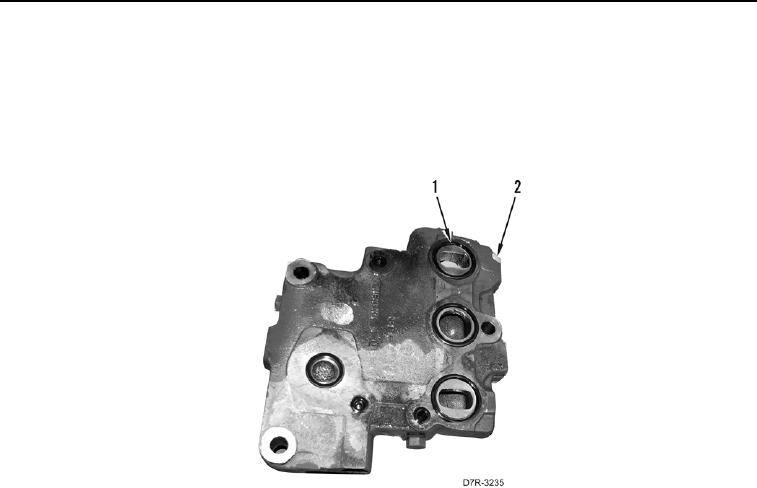
12.
Install
seven
new
O-rings (
Figure
21,
Item
1) on valve
bank
cover
(
Figure
21
,
Item
2).
Figure
21.
O-ring
Installation.
0212
0212-20