
TM 5-2410-241-23-3
0212
ASSEMBLY CONTINUED
N OT E
Valve bank is comprised of four valves, a cover, and a manifold. The bottom component is
the manifold, followed by the steering valve, the bulldozer lift valve, bulldozer tilt valve, and
the winch valve. The cover is the cap of the assembly.
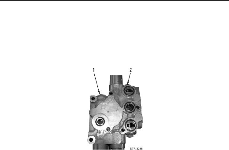
Install O-rings as noted during disassembly.
4. Install seven new O-rings (Figure 16, Item 2) on valve (Figure 16, Item 1).
Figure 16. O-ring Installation.
0212