• Home
  • Download PDF
  • Order CD-ROM
  • Order in Print
Figure 12. Bulldozer Tilt Control Valve Manifold.
Figure 14. Steering Control Valve Manifold.

Field Maintenance Manual 3 D7R Dozer Type I With Winch and Type II With Ripper
Page Navigation
  247    248    249    250    251  252  253    254    255    256    257  
img
.
TM 5-2410-241-23-3
0212
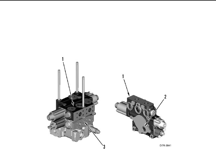
DISASSEMBLY CONTINUED
10. Remove valve (Figure 13, Item 1) from control valve assembly (Figure 13, Item 3).
N OT E
Note orientation and position of O-rings to aid assembly.
11. Remove seven O-rings (Figure 13, Item 2) from valve (Figure 13, Item 1). Discard O-rings.
Figure 13. Bulldozer Lift Control Valve Manifold.
0212
0212-13


Privacy Statement
Press Release
Contact

© Copyright Integrated Publishing, Inc.. All Rights Reserved.