
TM 5-2410-241-23-3
0212
DISASSEMBLY
000212
N OT E
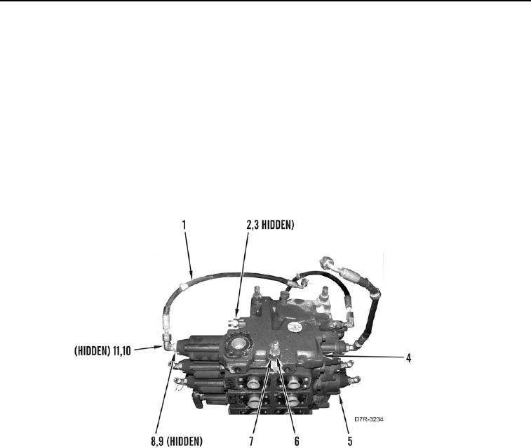
Note position and orientation of hoses and fittings to aid assembly.
1. Disconnect three hoses (Figure 8, Item 1) from fittings (Figure 8, Item 10). Remove O-rings (Figure 8, Item 11)
from fittings. Discard O-rings.
2. Remove two fittings (Figure 8, Item 2), and O-rings (Figure 8, Item 3) from cover (Figure 8, Item 4). Discard
O-rings.
3. Remove seven fittings (Figure 8, Item 8), and O-rings (Figure 8, Item 9). Discard O-rings.
4. Remove three nuts (Figure 8, Item 7), washers (Figure 8, Item 6), and cover (Figure 8, Item 4) from valve bank
(Figure 8, Item 5).
Figure 8. Valve Bank Cover Removal.
0212