• Home
  • Download PDF
  • Order CD-ROM
  • Order in Print
Figure 6. Hose Removal.
Figure 8. Valve Bank Cover Removal.

Field Maintenance Manual 3 D7R Dozer Type I With Winch and Type II With Ripper
Page Navigation
  241    242    243    244    245  246  247    248    249    250    251  
img
.
TM 5-2410-241-23-3
0212
REMOVAL CONTINUED
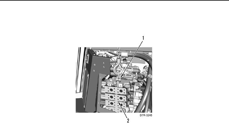
13. With assistance, remove valve bank (Figure 7, Item 2) from machine and place on clean work surface.
14. Remove lifting device and bracket link (Figure 7, Item 1) from valve bank (Figure 7, Item 2).
Figure 7.
Valve Bank Mounting.
0212
END OF TASK
0212-7


Privacy Statement
Press Release
Contact

© Copyright Integrated Publishing, Inc.. All Rights Reserved.