
TM 5-2410-241-23-3
0212
DISASSEMBLY CONTINUED
N OT E
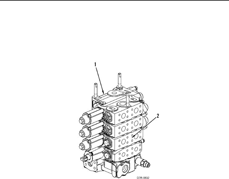
Valve bank is comprised of four valves, a cover, and a manifold. The top component is the
cover, followed by the winch valve, the bulldozer tilt valve, bulldozer lift valve, and the
steering valve. The manifold is the base of the assembly.
6. Remove valve (Figure 10, Item 1) from valve bank assembly (Figure 10, Item 2).
Figure 10.
Winch Valve Removal.
0212