
TM 5-2410-241-23-3
0212
REMOVAL CONTINUED
N OT E
Valve bank will need to be lifted approximately 1 in. (25 mm) to access and remove one
remaining hose at front of valve bank.
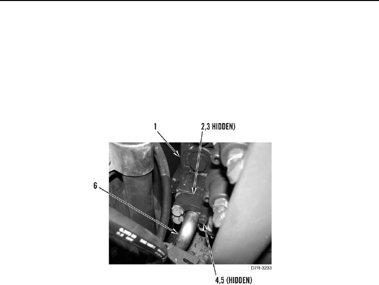
11. Using lifting device, raise valve bank (Figure 6, Item 1) to access hose (Figure 6, Item 6) at front of valve bank.
12. Remove four bolts (Figure 6, Item 4), washers (Figure 6, Item 5), two flanges (Figure 6, Item 2), and hose
(Figure 6, Item 6) from valve bank (Figure 6, Item 1). Remove O-ring (Figure 6, Item 3) from hose. Discard
O-ring.
Figure 6. Hose Removal.
0212