• Home
  • Download PDF
  • Order CD-ROM
  • Order in Print
Figure 2. Hose Connections at Front of Valve Bank.
Figure 5. Valve Bank Mounting.

Field Maintenance Manual 3 D7R Dozer Type I With Winch and Type II With Ripper
Page Navigation
  238    239    240    241    242  243  244    245    246    247    248  
img
.
TM 5-2410-241-23-3
0212
REMOVAL CONTINUED
N OT E
Note orientation and location of steering control link to aid installation.
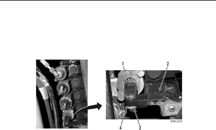
5. Remove two cotter pins (Figure 4, Item 4) and washers (Figure 4, Item 3) from steering control link (Figure 4,
Item 1). Discard cotter pin.
6. Remove steering control valve link (Figure 4, Item 1) from steering control pivot (Figure 4, Item 2).
Figure 4. Disconnecting Steering Control Link.
0212
0212-4


Privacy Statement
Press Release
Contact

© Copyright Integrated Publishing, Inc.. All Rights Reserved.