
TM 5-2410-241-23-3
0211
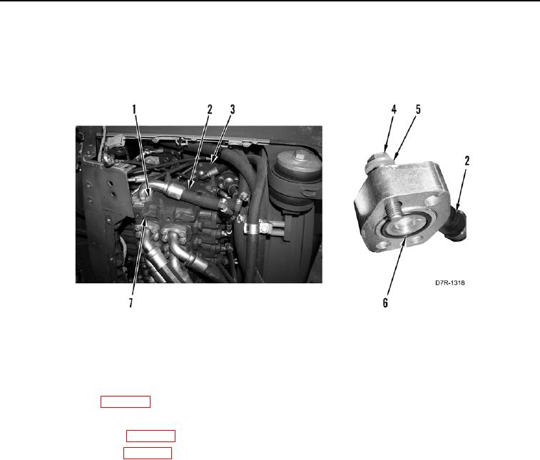
INSTALLATION CONTINUED
13. Install two new O-rings (Figure 26, Item 6) on hoses (Figure 26, Item 2).
14. Install two hoses (Figure 26, Item 2), flanges (Figure 26, Item 1), eight washers (Figure 26, Item 5), and bolts
(Figure 26, Item 4) on control valve (Figure 26, Item 7) and hydraulic tank (Figure 26, Item 3).
Figure 26. Top Hose.
0211
END OF TASK
FOLLOW-ON TASKS
000211
1. Install pilot valve (WP 0256).
2. Fill hydraulic system (WP 0184).
3. Install front floor plate (WP 0230).
4. Install rear floor plate (WP 0231).
5. Verify correct operation of machine (TM 5-2410-241-10).
END OF TASK
END OF WORK PACKAGE