• Home
  • Download PDF
  • Order CD-ROM
  • Order in Print
Figure 22. Front Side Hose.
Figure 24. Hoses and Lines.

Field Maintenance Manual 3 D7R Dozer Type I With Winch and Type II With Ripper
Page Navigation
  231    232    233    234    235  236  237    238    239    240    241  
img
.
TM 5-2410-241-23-3
0211
INSTALLATION CONTINUED
N OT E
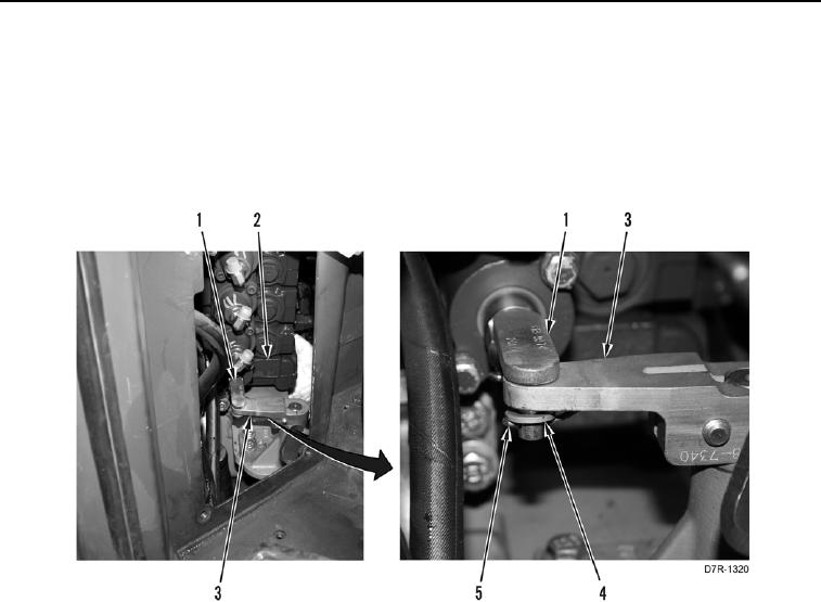
Install steering control linkage as noted during removal.
7. Install linkage (Figure 23, Item 1) on control valve (Figure 23, Item 2) and lever (Figure 23, Item 3).
8. Install two washers (Figure 23, Item 4) and new cotter pins (Figure 23, Item 5) on linkage (Figure 23, Item 1).
Figure 23. Control Lever Linkage.
0211
0211-24


Privacy Statement
Press Release
Contact

© Copyright Integrated Publishing, Inc.. All Rights Reserved.