• Home
  • Download PDF
  • Order CD-ROM
  • Order in Print
Figure 18. Steering Control Valve Manifold.
Figure 20. Control Valve Assembly.

Field Maintenance Manual 3 D7R Dozer Type I With Winch and Type II With Ripper
Page Navigation
  227    228    229    230    231  232  233    234    235    236    237  
img
.
TM 5-2410-241-23-3
0211
ASSEMBLY CONTINUED
N OT E
Install O-rings as noted during disassembly.
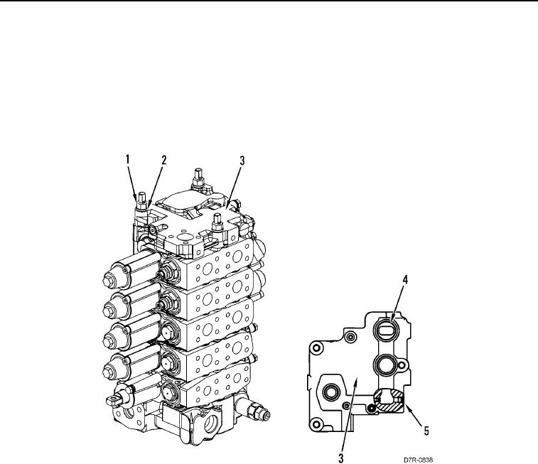
14. Install seven new O-rings (Figure 19, Item 4) on cover (Figure 19, Item 3).
15. Install cover (Figure 19, Item 3), three washers (Figure 19, Item 2), and nuts (Figure 19, Item 1) on control
valve assembly.
Figure 19. Control Valve Assembly.
0211
0211-20


Privacy Statement
Press Release
Contact

© Copyright Integrated Publishing, Inc.. All Rights Reserved.