
TM 5-2410-241-23-3
0211
INSTALLATION CONTINUED
N OT E
Install hoses and lines as noted during removal.
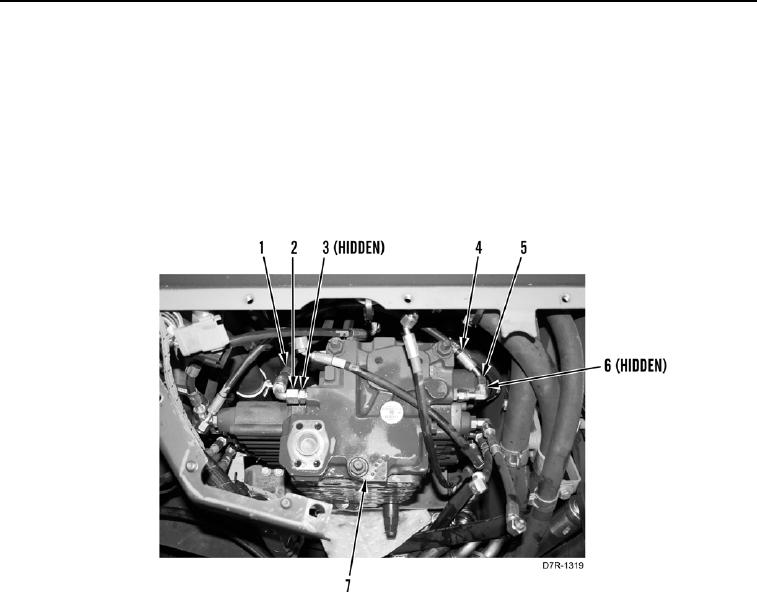
9. Install six new O-rings (Figure 24, Item 6), hoses (Figure 24, Item 4), and tighten tube nuts (Figure 24, Item 5)
on rear side of control valve (Figure 24, Item 7).
10. Install five new O-rings (Figure 24, Item 3), hoses (Figure 24, Item 2), and tighten tube nuts (Figure 24, Item 1)
on front side of control valve (Figure 24, Item 7).
Figure 24. Hoses and Lines.
0211