
TM 5-2410-241-23-3
0211
ASSEMBLY CONTINUED
N OT E
Remove plugs from fitting ports.
Install fittings as noted during removal.
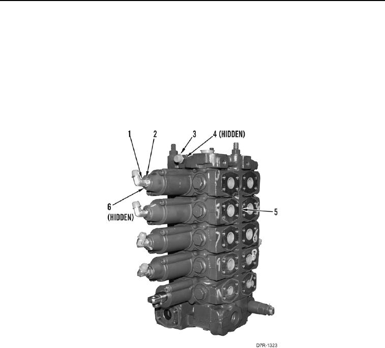
16. Install new O-ring (Figure 20, Item 4) and fitting (Figure 20, Item 3) on control valve assembly (Figure 20,
Item 5).
17. Install 10 new O-rings (Figure 20, Item 6), elbow fittings (Figure 20, Item 1), and nuts (Figure 20, Item 2) on
control valve assembly (Figure 20, Item 5).
Figure 20. Control Valve Assembly.
0211
END OF TASK