
TM 5-2410-241-23-3
0211
INSTALLATION CONTINUED
N OT E
Remove plugs from all lines, hoses and tubes.
Install hoses and lines as noted during removal.
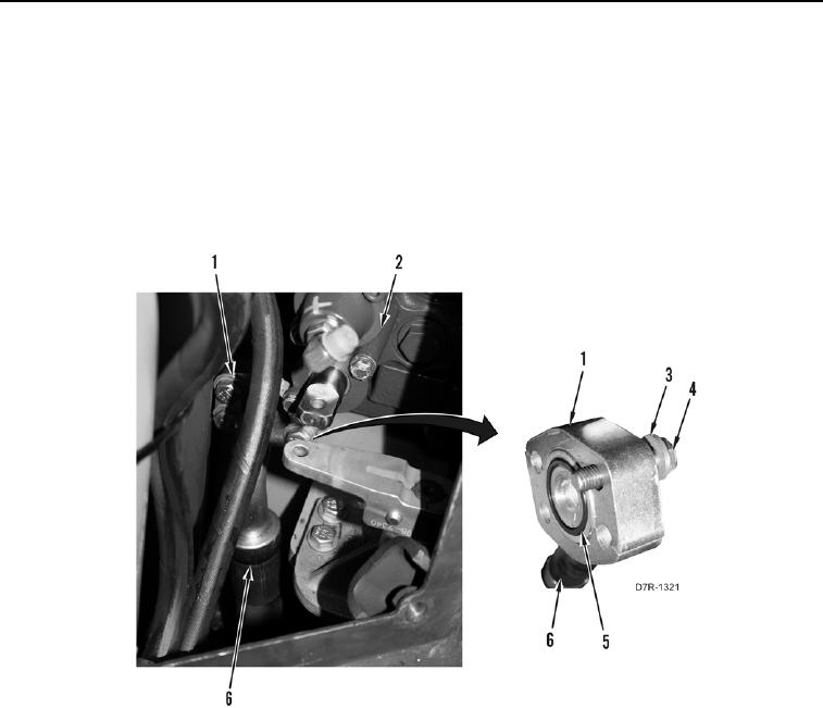
5. Install new O-ring (Figure 22, Item 5) on hose (Figure 22, Item 6).
6. Install hose (Figure 22, Item 6), flange (Figure 22, Item 1), four washers (Figure 22, Item 3), and bolts
(Figure 22, Item 4) on control valve (Figure 22, Item 2)
Figure 22. Front Side Hose.
0211